One-Dimensional Analysis
Let us return to the situation of Fig. 7-2 but now consider the force to be in the positive direction of the x axis and the force magnitude to vary with position x. Thus, as the bead (particle) moves, the magnitude F(x) of the force doing work on it changes. Only the magnitude of this variable force changes, not its direction, and the magnitude at any position does not change with time.
Figure 7-13a shows a plot of such a one-dimensional variable force. We want an expression for the work done on the particle by this force as the particle moves from an initial point xi to a final point xf. However, we cannot use Eq. 7-7 (W = Fd cos ![]() ) because it applies only for a constant force
) because it applies only for a constant force ![]() . Here, again, we shall use calculus. We divide the area under the curve of Fig. 7-13a into a number of narrow strips of width Δx (Fig. 7-13b). We choose Δx small enough to permit us to take the force F(x) as being reasonably constant over that interval. We let Fj,avg be the average value of F(x) within the jth interval. Then in Fig. 7-13b, Fj,avg is the height of the jth strip.
. Here, again, we shall use calculus. We divide the area under the curve of Fig. 7-13a into a number of narrow strips of width Δx (Fig. 7-13b). We choose Δx small enough to permit us to take the force F(x) as being reasonably constant over that interval. We let Fj,avg be the average value of F(x) within the jth interval. Then in Fig. 7-13b, Fj,avg is the height of the jth strip.
With Fj,avg considered constant, the increment (small amount) of work ΔWj done by the force in the jth interval is now approximately given by Eq. 7-7 and is

In Fig. 7-13b, ΔWj is then equal to the area of the jth rectangular, shaded strip.
To approximate the total work W done by the force as the particle moves from xi to xf, we add the areas of all the strips between xi and xf in Fig. 7-13b:

Equation 7-30 is an approximation because the broken “skyline” formed by the tops of the rectangular strips in Fig. 7-13b only approximates the actual curve of F(x).
We can make the approximation better by reducing the strip width Δx and using more strips, as in Fig. 7-13c. In the limit, we let the strip width approach zero; the number of strips then becomes infinitely large and we have, as an exact result,

This limit is exactly what we mean by the integral of the function F(x) between the limits xi and xf. Thus, Eq. 7-31 becomes
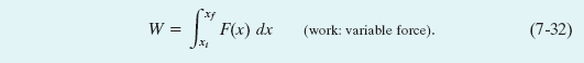
If we know the function F(x), we can substitute it into Eq. 7-32, introduce the proper limits of integration, carry out the integration, and thus find the work. (Appendix E contains a list of common integrals.) Geometrically, the work is equal to the area between the F(x) curve and the x axis, between the limits xi and xf (shaded in Fig. 7-13d).
Three-Dimensional Analysis
Consider now a particle that is acted on by a three-dimensional force

in which the components Fx, Fy, and Fz can depend on the position of the particle; that is, they can be functions of that position. However, we make three simplifications: Fx may depend on x but not on y or z, Fy may depend on y but not on x or z, and Fz may depend on z but not on x or y. Now let the particle move through an incremental displacement

The increment of work dW done on the particle by ![]() during the displacement
during the displacement ![]() is, by Eq. 7-8,
is, by Eq. 7-8,

The work W done by ![]() while the particle moves from an initial position ri having coordinates (xi, yi, zi) to a final position rf having coordinates (xf, yf, zf) is then
while the particle moves from an initial position ri having coordinates (xi, yi, zi) to a final position rf having coordinates (xf, yf, zf) is then
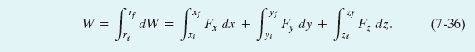
If ![]() has only an x component, then the y and z terms in Eq. 7-36 are zero and the equation reduces to Eq. 7-32.
has only an x component, then the y and z terms in Eq. 7-36 are zero and the equation reduces to Eq. 7-32.
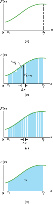
Fig. 7-13 (a) A one-dimensional force ![]() (x) plotted against the displacement x of a particle on which it acts. The particle moves from xi to xf. (b) Same as (a) but with the area under the curve divided into narrow strips. (c) Same as (b) but with the area divided into narrower strips. (d) The limiting case. The work done by the force is given by Eq. 7-32 and is represented by the shaded area between the curve and the x axis and between xi and xf.
(x) plotted against the displacement x of a particle on which it acts. The particle moves from xi to xf. (b) Same as (a) but with the area under the curve divided into narrow strips. (c) Same as (b) but with the area divided into narrower strips. (d) The limiting case. The work done by the force is given by Eq. 7-32 and is represented by the shaded area between the curve and the x axis and between xi and xf.
Work–Kinetic Energy Theorem with a Variable Force
Equation 7-32 gives the work done by a variable force on a particle in a one-dimensional situation. Let us now make certain that the calculated work is indeed equal to the change in kinetic energy of the particle, as the work–kinetic energy theorem states.
Consider a particle of mass m, moving along an x axis and acted on by a net force F(x) that is directed along that axis. The work done on the particle by this force as the particle moves from an initial position xi to a final position xf is given by Eq. 7-32 as
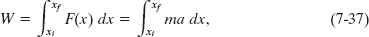
in which we use Newton’s second law to replace F(x) with ma. We can write the quantity ma dx in Eaq. 7-37 as
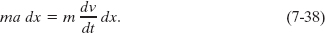
From the chain rule of calculus, we have
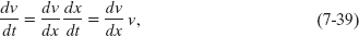
and Eq. 7-38 becomes

Substituting Eq. 7-40 into Eq. 7-37 yields
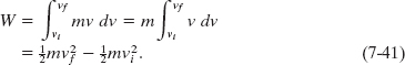
Note that when we change the variable from x to v we are required to express the limits on the integral in terms of the new variable. Note also that because the mass m is a constant, we are able to move it outside the integral.
Recognizing the terms on the right side of Eq. 7-41 as kinetic energies allows us to write this equation as
W = Kf − Ki = ΔK,
which is the work–kinetic energy theorem.
In an epidural procedure, the feel a doctor has for the needle’s penetration is the variable force that must be applied to advance the needle through the tissues. Figure 7-14a is a graph of the force magnitude F versus displacement x of the needle tip in a typical epidural procedure. (The line segments have been straightened somewhat from the original data.) As x increases from 0, the skin resists the needle, but at x = 8.0 mm the force is finally great enough to pierce the skin, and then the required force decreases. Similarly, the needle finally pierces the interspinous ligament at x = 18 mm and the relatively tough ligamentum flavum at x = 30 mm. The needle then enters the epidural space (where it is to deliver the anesthetic fluid), and the force drops sharply. A new doctor must learn this pattern of force versus displacement to recognize when to stop pushing on the needle. Thus this is the pattern to be programmed into a virtual-reality simulation of an epidural procedure. How much work W is done by the force exerted on the needle to get the needle to the epidural space at x = 30 mm?
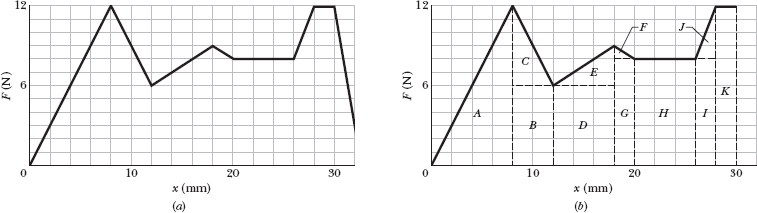
Fig. 7-14 (a) The force magnitude F versus the displacement x of the needle in an epidural procedure. (b) Breaking up the region between the plotted curve and the displacement axis to calculate the area.
Solution: One Key Idea here is that we can calculate the work W done by a variable force F(x) by integrating the force versus position x. Equation 7-32 tells us that

We want the work done by the force during the displacement from xi = 0 to xf = 0.030 m.
A second Key Idea is that we can evaluate the integral by finding the area under the curve on the graph of Fig. 7-14a.
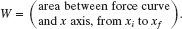
Because our graph consists of straight-line segments, we can find the area by splitting the region below the curve into rectangular and triangular regions, as shown in Fig. 7-14b. For example, the area in triangular region A is

Once we’ve calculated the areas for all the labeled regions in Fig. 7-14b, we find that the total work is
Force ![]() particle, changing only the kinetic energy of the particle. How much work is done on the particle as it moves from coordinates (2 m, 3 m) to (3 m, 0 m)? Does the speed of the particle increase, decrease, or remain the same?
particle, changing only the kinetic energy of the particle. How much work is done on the particle as it moves from coordinates (2 m, 3 m) to (3 m, 0 m)? Does the speed of the particle increase, decrease, or remain the same?
Solution: The Key Idea here is that the force is a variable force because its x component depends on the value of x. Thus, we cannot use Eqs. 7-7 and 7-8 to find the work done. Instead, we must use Eq. 7-36 to integrate the force:
The positive result means that energy is transferred to the particle by force ![]() . Thus, the kinetic energy of the particle increases, and so its speed must also increase.
. Thus, the kinetic energy of the particle increases, and so its speed must also increase.
Leave a Reply