A heat engine, or more simply, an engine, is a device that extracts energy from its environment in the form of heat and does useful work. At the heart of every engine is a working substance. In a steam engine, the working substance is water, in both its vapor and its liquid form. In an automobile engine the working substance is a gasoline–air mixture. If an engine is to do work on a sustained basis, the working substance must operate in a cycle; that is, the working substance must pass through a closed series of thermodynamic processes, called strokes, returning again and again to each state in its cycle. Let us see what the laws of thermodynamics can tell us about the operation of engines.
A Carnot Engine
We have seen that we can learn much about real gases by analyzing an ideal gas, which obeys the simple law pV = nRT. This is a useful plan because, although an ideal gas does not exist, any real gas approaches ideal behavior as closely as you wish if its density is low enough. In much the same spirit we choose to study real engines by analyzing the behavior of an ideal engine.
![]() In an ideal engine, all processes are reversible and no wasteful energy transfers occur due to, say, friction and turbulence.
In an ideal engine, all processes are reversible and no wasteful energy transfers occur due to, say, friction and turbulence.
We shall focus on a particular ideal engine called a Carnot engine after the French scientist and engineer N. L. Sadi Carnot (pronounced “car-no”), who first proposed the engine’s concept in 1824. This ideal engine turns out to be the best (in principle) at using energy as heat to do useful work. Surprisingly, Carnot was able to analyze the performance of this engine before the first law of thermodynamics and the concept of entropy had been discovered.
Figure 20-7 shows schematically the operation of a Carnot engine. During each cycle of the engine, the working substance absorbs energy |QH| as heat from a thermal reservoir at constant temperature TH and discharges energy |QL| as heat to a second thermal reservoir at a constant lower temperature TL.
Figure 20-8 shows a p–V plot of the Carnot cycle—the cycle followed by the working substance. As indicated by the arrows, the cycle is traversed in the clock-wise direction. Imagine the working substance to be a gas, confined to an insulating cylinder with a weighted, movable piston. The cylinder may be placed at will on either of the two thermal reservoirs, as in Fig. 20-6, or on an insulating slab. Figure 20-8 shows that, if we place the cylinder in contact with the high-temperature reservoir at temperature TH, heat |QH| is transferred to the working substance from this reservoir as the gas undergoes an isothermal expansion from volume Va to volume Vb. Similarly, with the working substance in contact with the low-temperature reservoir at temperature TL, heat |QL| is transferred from the working substance to the low-temperature reservoir as the gas undergoes an isothermal compression from volume Vc to volume Vd.
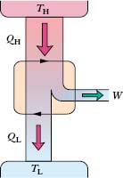
Fig. 20-7 The elements of a Carnot engine. The two black arrowheads on the central loop suggest the working substance operating in a cycle, as if on a p–V plot. Energy |QH| is transferred as heat from the high-temperature reservoir at temperature TH to the working substance. Energy |QL| is transferred as heat from the working substance to the low-temperature reservoir at temperature TL. Work W is done by the engine (actually by the working substance) on something in the environment.
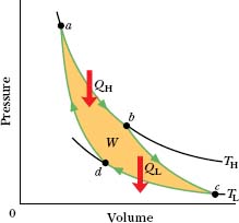
Fig. 20-8 A pressure–volume plot of the cycle followed by the working substance of the Carnot engine in Fig. 20-7. The cycle consists of two isothermal (ab and cd) and two adiabatic processes (bc and da). The shaded area enclosed by the cycle is equal to the work W per cycle done by the Carnot engine.
In the engine of Fig. 20-7, we assume that heat transfers to or from the working substance can take place only during the isothermal processes ab and cd of Fig. 20-8, Therefore, processes bc and da in that figure, which connect the two isotherms at temperatures TH and TL, must be (reversible) adiabatic processes; that is, they must be processes in which no energy is transferred as heat. To ensure this during processes bc and da the cylinder is placed on an insulating slab as the volume of the working substance is changed.
During the consecutive processes ab and bc of Fig. 20-8, the working substance is expanding and thus doing positive work as it raises the weighted piston. This work is represented in Fig. 20-8 by the area under curve abc. During the consecutive processes cd and da, the working substance is being compressed, which means that it is doing negative work on its environment or, equivalently, that its environment is doing work on it as the loaded piston descends. This work is represented by the area under curve cda. The net work per cycle, which is represented by W in both Figs. 20-7 and 20-8, is the difference between these two areas and is a positive quantity equal to the area enclosed by cycle abcda in Fig. 20-8. This work W is performed on some outside object, such as a load to be lifted.
Equation 20-1 (ΔS = ∫ dQ/T) tells us that any energy transfer as heat must involve a change in entropy. To illustrate the entropy changes for a Carnot engine, we can plot the Carnot cycle on a temperature-entropy (T–S) diagram as shown in Fig. 20-9. The lettered points a, b, c, and d in Fig. 20-9 correspond to the lettered points in the p–V diagram in Fig. 20-8. The two horizontal lines in Fig. 20-9 correspond to the two isothermal processes of the Carnot cycle (because the temperature is constant). Process ab is the isothermal expansion of the cycle. As the working substance (reversibly) absorbs energy |QH| as heat at constant temperature TH during the expansion, its entropy increases. Similarly, during the isothermal compression cd, the working substance (reversibly) loses energy |QL| as heat at constant temperature TL, and its entropy decreases.
The two vertical lines in Fig. 20-9 correspond to the two adiabatic processes of the Carnot cycle. Because no energy is transferred as heat during the two processes, the entropy of the working substance is constant during them.
The Work To calculate the net work done by a Carnot engine during a cycle, let us apply Eq. 18-26, the first law of thermodynamics (ΔEint = Q − W), to the working substance. That substance must return again and again to any arbitrarily selected state in the cycle. Thus, if X represents any state property of the working substance, such as pressure, temperature, volume, internal energy, or entropy, we must have ΔX = 0 for every cycle. It follows that ΔEint = 0 for a complete cycle of the working substance. Recalling that Q in Eq. 18-26 is the net heat transfer per cycle and W is the net work, we can write the first law of thermodynamics for the Carnot cycle as

Entropy Changes In a Carnot engine, there are two (and only two) reversible energy transfers as heat, and thus two changes in the entropy of the working substance—one at temperature TH and one at TL. The net entropy change per cycle is then

Here ΔSH is positive because energy |QH| is added to the working substance as heat (an increase in entropy) and ΔSL is negative because energy |QL| is removed from the working substance as heat (a decrease in entropy). Because entropy is a state function, we must have ΔS = 0 for a complete cycle. Putting ΔS = 0 in Eq. 20-7 requires that
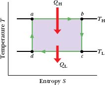
Fig. 20-9 The Carnot cycle of Fig. 20-8 plotted on a temperature– entropy diagram. During processes ab and cd the temperature remains constant. During processes bc and da the entropy remains constant.
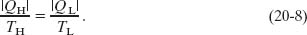
Note that, because TH > TL, we must have |QH| > |QL|; that is, more energy is extracted as heat from the high-temperature reservoir than is delivered to the low-temperature reservoir.
We shall now use Eqs. 20-6 and 20-8 to derive an expression for the efficiency of a Carnot engine.
Efficiency of a Carnot Engine
The purpose of any engine is to transform as much of the extracted energy QH into work as possible. We measure its success in doing so by its thermal efficiency ε, defined as the work the engine does per cycle (“energy we get”) divided by the energy it absorbs as heat per cycle (“energy we pay for”):

For a Carnot engine we can substitute for W from Eq. 20-6 to write Eq. 20-9 as

Using Eq. 20-8 we can write this as

where the temperatures TL and TH are in kelvins. Because TL < TH, the Carnot engine necessarily has a thermal efficiency less than unity—that is, less than 100%. This is indicated in Fig. 20-7, which shows that only part of the energy extracted as heat from the high-temperature reservoir is available to do work, and the rest is delivered to the low-temperature reservoir. We shall show in Section 20-7 that no real engine can have a thermal efficiency greater than that calculated from Eq. 20-11.
Inventors continually try to improve engine efficiency by reducing the energy |QL| that is “thrown away” during each cycle. The inventor’s dream is to produce the perfect engine, diagrammed in Fig. 20-10, in which |QL| is reduced to zero and |QH| is converted completely into work. Such an engine on an ocean liner, for example, could extract energy as heat from the water and use it to drive the propellers, with no fuel cost. An automobile fitted with such an engine could extract energy as heat from the surrounding air and use it to drive the car, again with no fuel cost. Alas, a perfect engine is only a dream: Inspection of Eq. 20-11 shows that we can achieve 100% engine efficiency (that is, ε = 1) only if TL = 0 or TH → ∞, requirements that are impossible to meet. Instead, decades of practical engineering experience have led to the following alternative version of the second law of thermodynamics:
![]() No series of processes is possible whose sole result is the transfer of energy as heat from a thermal reservoir and the complete conversion of this energy to work.
No series of processes is possible whose sole result is the transfer of energy as heat from a thermal reservoir and the complete conversion of this energy to work.
In short, there are no perfect engines.
To summarize: The thermal efficiency given by Eq. 20-11 applies only to Carnot engines. Real engines, in which the processes that form the engine cycle are not reversible, have lower efficiencies. If your car were powered by a Carnot engine, it would have an efficiency of about 55% according to Eq. 20-11; its actual efficiency is probably about 25%. A nuclear power plant (Fig. 20-11), taken in its entirety, is an engine. It extracts energy as heat from a reactor core, does work by means of a turbine, and discharges energy as heat to a nearby river. If the power plant operated as a Carnot engine, its efficiency would be about 40%; its actual efficiency is about 30%. In designing engines of any type, there is simply no way to beat the efficiency limitation imposed by Eq. 20-11.
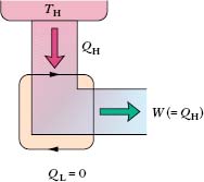
Fig. 20-10 The elements of a perfect engine—that is, one that converts heat QH from a high-tempera-ture reservoir directly to work W with 100% efficiency.
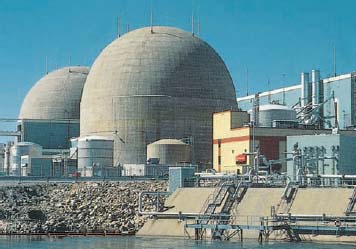
Fig. 20-11 The North Anna nuclear power plant near Charlottesville, Virginia, which generates electric energy at the rate of 900 MW. At the same time, by design, it discards energy into the nearby river at the rate of 2100 MW. This plant and all others like it throw away more energy than they deliver in useful form. They are real counterparts of the ideal engine of Fig. 20-7.
Stirling Engine
Equation 20-11 applies not to all ideal engines but only to those that can be represented as in Fig. 20-8—that is, to Carnot engines. For example, Fig. 20-12 shows the operating cycle of an ideal Stirling engine. Comparison with the Carnot cycle of Fig. 20-8 shows that each engine has isothermal heat transfers at temperatures TH and TL. However, the two isotherms of the Stirling engine cycle are connected, not by adiabatic processes as for the Carnot engine but by constant-volume processes. To increase the temperature of a gas at constant volume reversibly from TL to TH (process da of Fig. 20-12) requires a transfer of energy as heat to the working substance from a thermal reservoir whose temperature can be varied smoothly between those limits. Also, a reverse transfer is required in process bc. Thus, reversible heat transfers (and corresponding entropy changes) occur in all four of the processes that form the cycle of a Stirling engine, not just two processes as in a Carnot engine. Thus, the derivation that led to Eq. 20-11 does not apply to an ideal Stirling engine. More important, the efficiency of an ideal Stirling engine is lower than that of a Carnot engine operating between the same two temperatures. Real Stirling engines have even lower efficiencies.
The Stirling engine was developed in 1816 by Robert Stirling. This engine, long neglected, is now being developed for use in automobiles and spacecraft. A Stirling engine delivering 5000 hp (3.7 MW) has been built.
![]() CHECK POINT 3 Three Carnot engines operate between reservoir temperatures of (a) 400 and 500 K, (b) 600 and 800 K, and (c) 400 and 600 K. Rank the engines according to their thermal efficiencies, greatest first.
CHECK POINT 3 Three Carnot engines operate between reservoir temperatures of (a) 400 and 500 K, (b) 600 and 800 K, and (c) 400 and 600 K. Rank the engines according to their thermal efficiencies, greatest first.
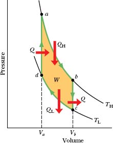
Fig. 20-12 A p–V plot for the working substance of an ideal Stirling engine, with the working substance assumed for convenience to be an ideal gas.
Imagine a Carnot engine that operates between the temperatures TH = 850 K and TL = 300 K. The engine performs 1200 J of work each cycle, which takes 0.25 s.
(a) What is the efficiency of this engine?
Solution: The Key Idea here is that the efficiency ε of a Carnot engine depends only on the ratio TL/TH of the temperatures (in kelvins) of the thermal reservoirs to which it is connected. Thus, from Eq. 20-11, we have

(b) What is the average power of this engine?
Solution: Here the Key Idea is that the average power P of an engine is the ratio of the work W it does per cycle to the time t that each cycle takes. For this Carnot engine, we find

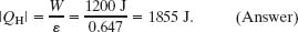
(c) How much energy |QH| is extracted as heat from the high-temperature reservoir every cycle?
Solution: Now the Key Idea is that for any engine, including a Carnot engine, the efficiency ε is the ratio of the work W that is done per cycle to the energy |QH| that is extracted as heat from the high-temperature reservoir per cycle (ε = W/|QH|). Thus,
(d) How much energy |QL| is delivered as heat to the low-temperature reservoir every cycle?
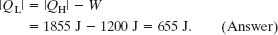
Solution: The Key Idea here is that for a Carnot engine, the work W done per cycle is equal to the difference in the energy transfers as heat: |QH| − |QL|, as in Eq. 20-6. Thus, we have
(e) By how much does the entropy of the working substance change as a result of the energy transferred to it from the high-temperature reservoir? From it to the low-temperature reservoir?
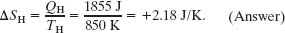
Solution: The Key Idea here is that the entropy change ΔS during a transfer of energy as heat Q at constant temperature T is given by Eq. 20-2 (ΔS = Q/T). Thus, for the positive transfer of energy QH from the high-temperature reservoir at TH, the change in the entropy of the working substance is
Similarly, for the negative transfer of energy QL to the low-temperature reservoir at TL, we have
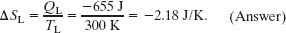
Note that the net entropy change of the working substance for one cycle is zero, as we discussed in deriving Eq. 20-8.
An inventor claims to have constructed an engine that has an efficiency of 75% when operated between the boiling and freezing points of water. Is this possible?
Solution: The Key Idea here is that the efficiency of a real engine (with its irreversible processes and wasteful energy transfers) must be less than the efficiency of a Carnot engine operating between the same two temperatures. From Eq. 20-11, we find that the efficiency of a Carnot engine operating between the boiling and freezing points of water is
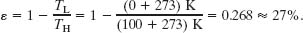
Thus, the claimed efficiency of 75% for a real engine operating between the given temperatures is impossible.
PROBLEM – SOLVING TACTICS
TACTIC 1 :
The Language of Thermodynamics
A rich but sometimes misleading language is used in scientific and engineering studies of thermodynamics. You may see statements that say heat is added, absorbed, subtracted, extracted, rejected, discharged, discarded, withdrawn, delivered, gained, lost, transferred, or expelled, or that it flows from one body to another (as if it were a liquid). You may also see statements that describe a body as having heat (as if heat can be held or possessed) or that its heat is increased or decreased. You should always keep in mind what is meant by the term heat in science and engineering:
![]() Heat is energy that is transferred from one body to another body due to a difference in the temperatures of the bodies.
Heat is energy that is transferred from one body to another body due to a difference in the temperatures of the bodies.
When we identify one of the bodies as being our system of interest, any such transfer of energy into the system is positive heat Q, and any such transfer out of the system is negative heat Q.
The term work also requires close attention. You may see statements that say work is produced or generated, or combined with heat or changed from heat. Here is what is meant by the term work:
![]() Work is energy that is transferred from one body to another body due to a force that acts between them.
Work is energy that is transferred from one body to another body due to a force that acts between them.
When we identify one of the bodies as being our system of interest, any such transfer of energy out of the system is either positive work W done by the system or negative work W done on the system. Any such transfer of energy into the system is negative work done by the system or positive work done on the system. (The preposition that is used is important.) Obviously, this can be confusing—whenever you see the term work, read carefully.
Leave a Reply