A wave sent along a stretched, taut string is the simplest mechanical wave. If you give one end of a stretched string a single up-and-down jerk, a wave in the form of a single pulse travels along the string, as in Fig. 16-1a. This pulse and its motion can occur because the string is under tension. When you pull your end of the string upward, it begins to pull upward on the adjacent section of the string via tension between the two sections. As the adjacent section moves upward, it begins to pull the next section upward, and so on. Meanwhile, you have pulled down on your end of the string. As each section moves upward in turn, it begins to be pulled back downward by neighboring sections that are already on the way down. The net result is that a distortion in the string’s shape (the pulse) moves along the string at some velocity  .
.
If you move your hand up and down in continuous simple harmonic motion, a continuous wave travels along the string at velocity . Because the motion of your hand is a sinusoidal function of time, the wave has a sinusoidal shape at any given instant, as in Fig. 16-1b; that is, the wave has the shape of a sine curve or a cosine curve.
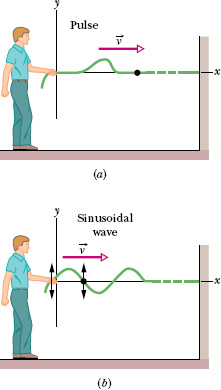
Fig. 16-1 (a) A single pulse is sent along a stretched string. A typical string element (marked with a dot) moves up once and then down as the pulse passes. The element’s motion is perpendicular to the wave’s direction of travel, so the pulse is a transverse wave. (b) A sinusoidal wave is sent along the string. A typical string element moves up and down continuously as the wave passes. This too is a transverse wave.
We consider here only an “ideal” string, in which no friction-like forces within the string cause the wave to die out as it travels along the string. In addition, we assume that the string is so long that we need not consider a wave rebounding from the far end.
One way to study the waves of Fig. 16-1 is to monitor the wave forms (shapes of the waves) as they move to the right. Alternatively, we could monitor the motion of an element of the string as the element oscillates up and down while a wave passes through it. We would find that the displacement of every such oscillating string element is perpendicular to the direction of travel of the wave, as indicated in Fig. 16-1b. This motion is said to be transverse, and the wave is said to be a transverse wave.
Figure 16-2 shows how a sound wave can be produced by a piston in a long, air-filled pipe. If you suddenly move the piston rightward and then leftward, you can send a pulse of sound along the pipe. The rightward motion of the piston moves the elements of air next to it rightward, changing the air pressure there. The increased air pressure then pushes rightward on the elements of air somewhat farther along the pipe. Moving the piston leftward reduces the air pressure next to it. As a result, first the elements nearest the piston and then farther elements move leftward. Thus, the motion of the air and the change in air pressure travel rightward along the pipe as a pulse.
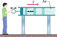
Fig. 16-2 A sound wave is set up in an air-filled pipe by moving a piston back and forth. Because the oscillations of an element of the air (represented by the dot) are parallel to the direction in which the wave travels, the wave is a longitudinal wave.
If you push and pull on the piston in simple harmonic motion, as is being done in Fig. 16-2, a sinusoidal wave travels along the pipe. Because the motion of the elements of air is parallel to the direction of the wave’s travel, the motion is said to be longitudinal, and the wave is said to be a longitudinal wave. In this lesson we focus on transverse waves, and string waves in particular; in Lesson 17 we focus on longitudinal waves, and sound waves in particular.
Both a transverse wave and a longitudinal wave are said to be traveling waves because they both travel from one point to another, as from one end of the string to the other end in Fig. 16-1 and from one end of the pipe to the other end in Fig. 16-2. Note that it is the wave that moves from end to end, not the material (string or air) through which the wave moves.
Seismic waves are waves that travel either through Earth’s interior or along the ground. Seismology stations are set up mainly to record seismic waves generated by earthquakes, but they also record seismic waves generated by any large release of energy near Earth’s surface, such as an explosion. As the seismic waves travel past a station, they oscillate a recording pen and the pen traces out a graph. Figure 16-3a is one of the graphs created by seismic waves from the sinking of the submarine Kursk. The first oscillations of the pen are marked with an arrow and were of small amplitude. Much stronger oscillations began about 134 s later.
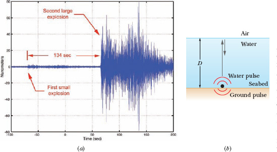
Fig. 16-3 (a) Graph made by a recording device as seismic waves from the Kursk passed the device. Amplitude is plotted vertically; time increases rightward. The first Kursk explosion produced the small-amplitude waves marked with an arrow. The next Kursk explosion produced waves of larger amplitude. (b) With the submarine sitting at depth D, the large explosion sent pulses both into the ground and up through the water.
From this, analysts concluded that the first seismic waves were generated by an onboard explosion, possibly a torpedo that failed to launch when fired. The explosion presumably breached the hull, started a fire, and sank the submarine. The later, much stronger seismic waves were generated after the submarine was sunk and were possibly generated when the fire caused several of the powerful missiles on board to explode simultaneously. These stronger waves arrived at seismology stations as pulses separated by a time interval Δt of about 0.11 s. To what depth D did the submarine sink?
Solution: Let us assume that the stronger explosion occurred after the Kursk was sitting on the ocean floor (the seabed). That explosion sent a pulse into the seabed and a pulse upward through the water (Fig. 16-3b). The pulse traveling through the water “bounced” several times between the water surface and the seabed. Each time it hit the seabed, it sent another pulse into the ground, and seismology stations detected those ground pulses as they arrived one after another. Thus, the time Δt between any two detected ground pulses was equal to the round-trip time for the water pulse to travel up to the water surface and back to the seabed. From Eq. 2-2 (vavg = Δx/Δt), we can relate the speed v of the water pulse to the round-trip distance 2D and the round-trip time Δt as

Waves travel through water at about 1500 m/s. Substituting this value and Δt = 0.11 s in Eq. 16-1, we find that the seismic data predicted the sunken Kursk was at a depth of about
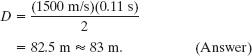
In fact, the wreck was discovered at a depth of about 115 m.
Leave a Reply