When you squeeze one end of a tube to get toothpaste out the other end, you are watching Pascal’s principle in action. This principle is also the basis for the Heimlich maneuver, in which a sharp pressure increase properly applied to the abdomen is transmitted to the throat, forcefully ejecting food lodged there. The principle was first stated clearly in 1652 by Blaise Pascal (for whom the unit of pressure is named):
![]() A change in the pressure applied to an enclosed incompressible fluid is transmitted undiminished to every portion of the fluid and to the walls of its container.
A change in the pressure applied to an enclosed incompressible fluid is transmitted undiminished to every portion of the fluid and to the walls of its container.
Demonstrating Pascal’s Principle
Consider the case in which the incompressible fluid is a liquid contained in a tall cylinder, as in Fig. 14-7. The cylinder is fitted with a piston on which a container of lead shot rests. The atmosphere, container, and shot exert pressure pext on the piston and thus on the liquid. The pressure p at any point P in the liquid is then

Let us add a little more lead shot to the container to increase pext by an amount Δpext. The quantities ρ, g, and h in Eq. 14-11 are unchanged, so the pressure change at P is

This pressure change is independent of h, so it must hold for all points within the liquid, as Pascal’s principle states.
Pascal’s Principle and the Hydraulic Lever
Figure 14-8 shows how Pascal’s principle can be made the basis of a hydraulic lever. In operation, let an external force of magnitude Fi be directed downward on the left-hand (or input) piston, whose surface area is Ai. An incompressible liquid in the device then produces an upward force of magnitude Fo on the right hand (or output) piston, whose surface area is Ao. To keep the system in equilibrium, there must be a downward force of magnitude F0 on the output piston from an external load (not shown). The force ![]() applied on the left and the downward force
applied on the left and the downward force ![]() from the load on the right produce a change Δp in the pressure of the liquid that is given by
from the load on the right produce a change Δp in the pressure of the liquid that is given by
so
Equation 14-13 shows that the output force Fo on the load must be greater than the input force Fi if Ao > Ai, as is the case in Fig. 14-8.
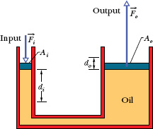
Fig. 14-8 A hydraulic arrangement that can be used to magnify a force ![]() . The work done is, however, not magnified and is the same for both the input and output forces.
. The work done is, however, not magnified and is the same for both the input and output forces.
If we move the input piston downward a distance di, the output piston moves upward a distance do, such that the same volume V of the incompressible liquid is displaced at both pistons. Then
V = Aidi = Aodo,
which we can write as
This shows that, if Ao > Ai (as in Fig. 14-8), the output piston moves a smaller distance than the input piston moves.
From Eqs. 14-13 and 14-14 we can write the output work as

which shows that the work W done on the input piston by the applied force is equal to the work W done by the output piston in lifting the load placed on it.
The advantage of a hydraulic lever is this:
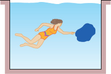
Fig. 14-9 A thin-walled plastic sack of water is in static equilibrium in the pool. The gravitational force on the sack must be balanced by a net upward force on it from the surrounding water.
![]() With a hydraulic lever, a given force applied over a given distance can be transformed to a greater force applied over a smaller distance.
With a hydraulic lever, a given force applied over a given distance can be transformed to a greater force applied over a smaller distance.
The product of force and distance remains unchanged so that the same work is done. However, there is often tremendous advantage in being able to exert the larger force. Most of us, for example, cannot lift an automobile directly but can with a hydraulic jack, even though we have to pump the handle farther than the automobile rises. In this device, the displacement di is accomplished not in a single stroke but over a series of small strokes.
Leave a Reply