In this section we examine four sample problems involving static equilibrium. In each, we select a system of one or more objects to which we apply the equations of equilibrium (Eqs. 12-7, 12-8, and 12-9). The forces involved in the equilibrium are all in the xy plane, which means that the torques involved are parallel to the z axis. Thus, in applying Eq. 12-9, the balance of torques, we select an axis parallel to the z axis about which to calculate the torques. Although Eq. 12-9 is satisfied for any such choice of axis, you will see that certain choices simplify the application of Eq. 12-9 by eliminating one or more unknown force terms.
Sample Problem 12-1
In Fig. 12-5a, a uniform beam, of length L and mass m = 1.8 kg, is at rest on two scales. A uniform block, with mass M = 2.7 kg, is at rest on the beam, with its center a distance L/4 from the beam’s left end. What do the scales read?
Solution: The first steps in the solution of any problem about static equilibrium are these: Clearly define the system to be analyzed and then draw a free-body diagram of it, indicating all the forces on the system. Here, let us choose the system as the beam and block taken together. Then the forces on the system are shown in the free-body diagram of Fig. 12-5b. (Choosing the system takes experience, and often there can be more than one good choice; see item 2 of Problem-Solving Tactic 1 below.)
The normal forces on the beam from the scales ![]() are on the left and
are on the left and ![]() on the right. The scale readings that we want are equal to the magnitudes of those forces. The gravitational force
on the right. The scale readings that we want are equal to the magnitudes of those forces. The gravitational force ![]() on the beam acts at the beam’s center of mass and is equal to m
on the beam acts at the beam’s center of mass and is equal to m![]() . Similarly, the gravitational force
. Similarly, the gravitational force ![]() on the block acts at the block’s center of mass and is equal to M
on the block acts at the block’s center of mass and is equal to M![]() . However, to simplify Fig. 12-5b, the block is represented by a dot within the boundary of the beam and
. However, to simplify Fig. 12-5b, the block is represented by a dot within the boundary of the beam and ![]() is drawn with its tail on that dot. (This shift of vector
is drawn with its tail on that dot. (This shift of vector ![]() along its line of action does not alter the torque due to
along its line of action does not alter the torque due to ![]() about any axis perpendicular to the figure.)
about any axis perpendicular to the figure.)
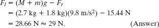
The Key Idea here is that, because the system is in static equilibrium, we can apply the balance of forces equations (Eqs. 12-7 and 12-8) and the balance of torques equation (Eq. 12-9) to it. The forces have no x components, so Eq. 12-7 (Fnet,x = 0) provides no information. For the y components, Eq. 12-8 (Fnet,y = 0) gives us

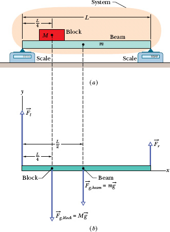
Fig. 12-5 (a) A beam of mass m supports a block of mass M. (b) A free-body diagram, showing the forces that act on the system beam + block.
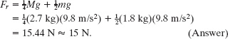
This equation contains two unknowns, the forces Fl and Fr, so we also need to use Eq. 12-9, the balance of torques equation. We can apply it to any rotation axis perpendicular to the plane of Fig. 12-5. Let us choose a rotation axis through the left end of the beam. We shall also use our general rule for assigning signs to torques: If a torque would cause an initially stationary body to rotate clockwise about the rotation axis, the torque is negative. If the rotation would be counterclockwise, the torque is positive. Finally, we shall write the torques in the form r ┴ F, where the moment arm r┴ is 0 for ![]() , L/2 for m
, L/2 for m![]() , and L for
, and L for ![]() .
.
We now can write the balancing equation (τnet,z = 0) as
(0)(Fl) − (L/4)(Mg) − (L/2)(mg) + (L)(Fr) = 0,
which gives us
Now, solving Eq. 12-18 for Fl and substituting this result, we find
Notice the strategy in the solution: When we wrote an equation for the balance of force components, we got stuck with two unknowns. If we had written an equation for the balance of torques around some arbitrary axis, we would have again gotten stuck with those two unknowns. However, because we chose the axis to pass through the point of application of one of the unknown forces, here ![]() , we did not get stuck. Our choice neatly eliminated that force from the torque equation, allowing us to solve for the other unknown force magnitude Fr. Then we returned to the equation for the balance of force components to find the remaining unknown force magnitude.
, we did not get stuck. Our choice neatly eliminated that force from the torque equation, allowing us to solve for the other unknown force magnitude Fr. Then we returned to the equation for the balance of force components to find the remaining unknown force magnitude.
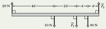
![]() CHECKPOINT 3 The figure gives an overhead view of a uniform rod in static equilibrium. (a) Can you find the magnitudes of unknown forces
CHECKPOINT 3 The figure gives an overhead view of a uniform rod in static equilibrium. (a) Can you find the magnitudes of unknown forces ![]() and
and ![]() by balancing the forces? (b) If you wish to find the magnitude of force
by balancing the forces? (b) If you wish to find the magnitude of force ![]() by using a single equation, where should you place a rotational axis? (c) The magnitude of
by using a single equation, where should you place a rotational axis? (c) The magnitude of ![]() turns out to be 65 N. What then is the magnitude of
turns out to be 65 N. What then is the magnitude of ![]() ?
?
Sample Problem 12-2
In Fig. 12-6a, a ladder of length L = 12 m and mass m = 45 kg leans against a slick (frictionless) wall. The ladder’s upper end is at height h = 9.3 m above the pavement on which the lower end rests (the pavement is not frictionless). The ladder’s center of mass is L/3 from the lower end. A firefighter of mass M = 72 kg climbs the ladder until her center of mass is L/2 from the lower end. What then are the magnitudes of the forces on the ladder from the wall and the pavement?
Solution: First, we choose our system as being the firefighter and ladder, together, and then we draw the free-body diagram of Fig. 12-6b. The firefighter is represented with a dot within the boundary of the ladder. The gravitational force on her is represented with its equivalent M![]() , and that vector has been shifted along its line of action, so that its tail is on the dot. (The shift does not alter a torque due to M
, and that vector has been shifted along its line of action, so that its tail is on the dot. (The shift does not alter a torque due to M![]() about any axis perpendicular to the figure.)
about any axis perpendicular to the figure.)
The only force on the ladder from the wall is the horizontal force ![]() (there cannot be a frictional force along a frictionless wall). The force
(there cannot be a frictional force along a frictionless wall). The force ![]() on the ladder from the pavement has a horizontal component
on the ladder from the pavement has a horizontal component ![]() that is a static frictional force and a vertical component
that is a static frictional force and a vertical component ![]() that is a normal force.
that is a normal force.
A Key Idea here is that the system is in static equilibrium, so the balancing equations (Eqs. 12-7 through 12-9) apply to it. Let us start with Eq. 12-9 (τnet,z = 0). To choose an axis about which to calculate the torques, note that we have unknown forces (![]() and
and ![]() ) at the two ends of the ladder. To eliminate, say,
) at the two ends of the ladder. To eliminate, say, ![]() from the calculation, we place the axis at point O, perpendicular to the figure. We also place the origin of an xy coordinate system at O. We can find torques about O with any of Eqs. 10-39 through 10-41, but Eq. 10-41 (τ = r ┴ F) is easiest to use here.
from the calculation, we place the axis at point O, perpendicular to the figure. We also place the origin of an xy coordinate system at O. We can find torques about O with any of Eqs. 10-39 through 10-41, but Eq. 10-41 (τ = r ┴ F) is easiest to use here.
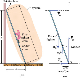
Fig. 12-6 (a) A firefighter climbs halfway up a ladder that is leaning against a frictionless wall. The pavement beneath the ladder is not frictionless. (b) A free-body diagram, showing the forces that act on the firefighter + ladder system. The origin O of a coordinate system is placed at the point of application of the unknown force ![]() (whose vector components
(whose vector components ![]() and
and ![]() are shown).
are shown).
To find the moment arm r┴ of ![]() , we draw a line of action through that vector (horizontal dashed line in Fig. 12-6b). Then r┴ is the perpendicular distance between O and the line of action. In Fig. 12-6b, r┴ extends along the y axis and is equal to the height h. We similarly draw lines of action for M
, we draw a line of action through that vector (horizontal dashed line in Fig. 12-6b). Then r┴ is the perpendicular distance between O and the line of action. In Fig. 12-6b, r┴ extends along the y axis and is equal to the height h. We similarly draw lines of action for M![]() and m
and m![]() and see that their moment arms extend along the x axis. For the distance a shown in Fig. 12-6a, the moment arms are a/2 (the firefighter is halfway up the ladder) and a/3 (the ladder’s center of mass is one-third of the way up the ladder), respectively. The moment arms for
and see that their moment arms extend along the x axis. For the distance a shown in Fig. 12-6a, the moment arms are a/2 (the firefighter is halfway up the ladder) and a/3 (the ladder’s center of mass is one-third of the way up the ladder), respectively. The moment arms for ![]() and
and ![]() are zero.
are zero.
Now, with torques written in the form r ┴ F, the balancing equation τnet,z = 0 becomes

(Recall our rule: A positive torque corresponds to counterclockwise rotation and a negative torque corresponds to clockwise rotation.)
Using the Pythagorean theorem, we find that
Then Eq. 12-19 gives us
Now we need to use the force balancing equations. The equation Fnet,x = 0 gives us

so
Fpx = Fw = 410 N. (Answer)
The equation Fnet,y = 0 gives us

Sample Problem 12-3
Figure 12-7a shows a safe, of mass M = 430 kg, hanging by a rope from a boom with dimensions a = 1.9 m and b = 2.5 m. The boom consists of a hinged beam and a horizontal cable. The uniform beam has a mass m of 85 kg; the masses of the cable and rope are negligible.
(a) What is the tension Tc in the cable? In other words, what is the magnitude of the force ![]() on the beam from the cable?
on the beam from the cable?
Solution: The system here is the beam alone, and the forces on it are shown in the free-body diagram of Fig. 12-7b. The force from the cable is ![]() . The gravitational force on the beam acts at the beam’s center of mass (at the beam’s center) and is represented by its equivalent m
. The gravitational force on the beam acts at the beam’s center of mass (at the beam’s center) and is represented by its equivalent m![]() . The vertical component of the force on the beam from the hinge is
. The vertical component of the force on the beam from the hinge is ![]() , and the horizontal component of the force from the hinge is
, and the horizontal component of the force from the hinge is ![]() . The force from the rope supporting the safe is
. The force from the rope supporting the safe is ![]() . Because beam, rope, and safe are stationary, the magnitude of
. Because beam, rope, and safe are stationary, the magnitude of ![]() is equal to the weight of the safe: Tr = Mg. We place the origin O of an xy coordinate system at the hinge.
is equal to the weight of the safe: Tr = Mg. We place the origin O of an xy coordinate system at the hinge.
One Key Idea here is that our system is in static equilibrium, so the balancing equations apply to it. Let us start with Eq. 12-9 (τnet,z = 0). Note that we are asked for the magnitude of force ![]() and not of forces
and not of forces ![]() and
and ![]() acting at the hinge, at point O. Thus, a second Key Idea is that, to eliminate
acting at the hinge, at point O. Thus, a second Key Idea is that, to eliminate ![]() and
and ![]() from the torque calculation, we should calculate torques about an axis that is perpendicular to the figure at point O. Then
from the torque calculation, we should calculate torques about an axis that is perpendicular to the figure at point O. Then ![]() and
and ![]() will have moment arms of zero. The lines of action for
will have moment arms of zero. The lines of action for ![]() ,
, ![]() , and m
, and m![]() are dashed in Fig. 12-7b. The corresponding moment arms are a, b, and b/2.
are dashed in Fig. 12-7b. The corresponding moment arms are a, b, and b/2.
Writing torques in the form of r ┴ F and using our rule about signs for torques, the balancing equation τnet,z = 0 becomes
(a)(Tc) − (b)(Tr) − (![]() b)(mg) = 0.
b)(mg) = 0.
Substituting Mg for Tr and solving for Tc, we find that
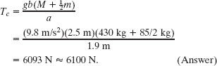
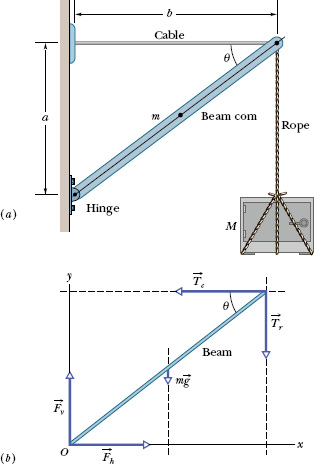
Fig. 12-7 (a) A heavy safe is hung from a boom consisting of a horizontal steel cable and a uniform beam. (b) A free-body diagram for the beam.
(b) Find the magnitude F of the net force on the beam from the hinge.
Solution: Now we want Fh and Fv so we can combine them to get F. Because we know Tc, our Key Idea here is to apply the force balancing equations to the beam. For the horizontal balance, we write Fnet,x = 0 as
Fh − Tc = 0,
and so
Fh = Tc = 6093 N.
For the vertical balance, we write Fnet,y = 0 as
Fv − mg − Tr = 0.
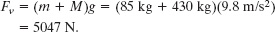
Substituting Mg for Tr and solving for Fv, we find that
From the Pythagorean theorem, we now have
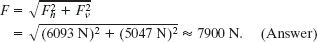
Note that F is substantially greater than either the combined weights of the safe and the beam, 5000 N, or the tension in the horizontal wire, 6100 N.
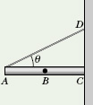
![]() CHECKPOINT 4 In the figure, a stationary 5 kg rod AC is held against a wall by a rope and friction between rod and wall. The uniform rod is 1 m long, and angle θ = 30°. (a) If you are to find the magnitude of the force
CHECKPOINT 4 In the figure, a stationary 5 kg rod AC is held against a wall by a rope and friction between rod and wall. The uniform rod is 1 m long, and angle θ = 30°. (a) If you are to find the magnitude of the force ![]() on the rod from the rope with a single equation, at what labeled point should a rotational axis be placed? With that choice of axis and counterclockwise torques positive, what is the sign of (b) the torque τw due to the rod’s weight and (c) the torque τr due to the pull on the rod by the rope? (d) Is the magnitude of τr greater than, less than, or equal to the magnitude of τw?
on the rod from the rope with a single equation, at what labeled point should a rotational axis be placed? With that choice of axis and counterclockwise torques positive, what is the sign of (b) the torque τw due to the rod’s weight and (c) the torque τr due to the pull on the rod by the rope? (d) Is the magnitude of τr greater than, less than, or equal to the magnitude of τw?
Sample Problem 12-4
Rock climbers who complain of acute pain along their fingers often remember exactly when the pain first appeared: They were using a crimp hold on an overhead support that may have been only a few millimeters deep. In this type of hold, the climber presses down with four fingers to gain purchase.
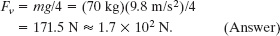
(a) Figure 12-8a shows a 70 kg climber hanging by only the crimp hold of one hand. Her feet touch the rock wall directly below her crimped fingers. Assume that the force from the horizontal ledge supporting her fingers is equally shared by the four fingers. What are the values of the horizontal component Fh and vertical component Fv of the force on each fingertip?
Solution: Our system is the climber, and Fig. 12-8a shows the forces ![]() that act on her. Force acts on each fingertip, with horizontal component Fh and vertical component Fv. Thus, the net force on the four fingertips has horizontal component 4Fh and vertical component 4Fv. The gravitational force
that act on her. Force acts on each fingertip, with horizontal component Fh and vertical component Fv. Thus, the net force on the four fingertips has horizontal component 4Fh and vertical component 4Fv. The gravitational force ![]() = m
= m![]() acts at her center of mass, and a normal force
acts at her center of mass, and a normal force ![]() from the wall acts on her feet at point O. (There is no vertical force from the wall on her feet.)
from the wall acts on her feet at point O. (There is no vertical force from the wall on her feet.)
A Key Idea here is that, because the system is in static equilibrium, we can apply Eqs. 12-7, 12-8, and 12-9 for the balance of forces and the balance of torques. The balance of forces equation Fnet,x = 0 leads to
−FN + 4Fh = 0.
However, we cannot solve this equation for Fh because we do not know the value of FN. The balance of forces equation Fnet,y = 0 leads to
4Fv − mg = 0,
which we can solve for Fv:
The third equation we need is the balance of torques equation, τnet,z = 0. Because we do not know or want the magnitude of ![]() , let’s calculate torques about an axis that is perpendicular to the figure at point O. To do so, we need the moment arm r┴ of each force acting on the climber. The moment arm for torques about O is 0 for
, let’s calculate torques about an axis that is perpendicular to the figure at point O. To do so, we need the moment arm r┴ of each force acting on the climber. The moment arm for torques about O is 0 for ![]() , 0.20 m for m
, 0.20 m for m![]() , 2.0 m for Fh, and 0 for Fv. Applying Eq. 11-17 (τ = r ┴ F), we can now rewrite τnet,z = 0 as
, 2.0 m for Fh, and 0 for Fv. Applying Eq. 11-17 (τ = r ┴ F), we can now rewrite τnet,z = 0 as
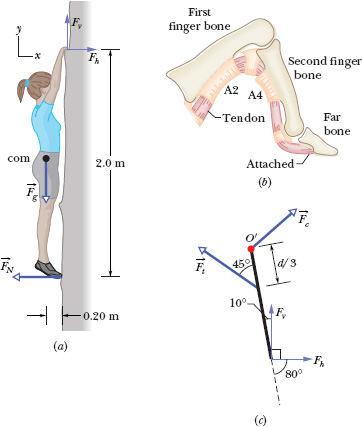
Fig. 12-8 (a) A climber hangs by only a crimp hold of one hand. The forces on her are indicated. (b) A tendon runs through the A2 and A4 pulleys on the finger bones. (c) A simplifed drawing of the forces acting on the second finger bone in a crimp hold.
(0)FN + (0.20 m)(mg) − (2.0 m)(4Fh) + (0)(4Fv) = 0.
Solving for Fh and substituting known data give us
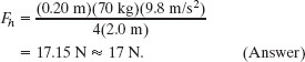
(b) Figure 12-8b shows details of a finger. A tendon that runs from muscles in the forearm is attached to the far bone in the finger. Along the way, the tendon runs through several guiding sheaths called pulleys. The A2 pulley is attached to the first finger bone; the A4 pulley is attached to the second finger bone. To pull the finger toward the palm, the forearm muscles pull the tendon through the pulleys, much like strings on a marionette can be pulled to move parts of the marionette.
Figure 12-8c is a simplified diagram of the second finger bone, which has length d. The tendon’s pull ![]() on the bone acts at the point where the tendon enters the A4 pulley, at distance d/3 along the bone. For the crimp-hold results of part (a) and for the angles shown in Fig. 12-8c, what is the magnitude of
on the bone acts at the point where the tendon enters the A4 pulley, at distance d/3 along the bone. For the crimp-hold results of part (a) and for the angles shown in Fig. 12-8c, what is the magnitude of ![]() ?
?
Solution: Our system is now the second finger bone. The Key Idea is that because the system is in equilibrium, we can again apply the balance equations—in particular, the equation for the balance of torques (τnet,z = 0). Because we do not know or want force ![]() at point O′, where the first and second bones meet, we calculate torques about that point. We are letting the unknown length of the second bone be d; let us use Eq. 11-15 (τ = rF sin
at point O′, where the first and second bones meet, we calculate torques about that point. We are letting the unknown length of the second bone be d; let us use Eq. 11-15 (τ = rF sin ![]() ) to calculate torques. The values of r are 0 for
) to calculate torques. The values of r are 0 for ![]() , d/3 for
, d/3 for ![]() , and d for Fh and Fv. We can now write τnet,z = 0 as
, and d for Fh and Fv. We can now write τnet,z = 0 as
(0)Fc − ![]() Ft sin 45° + dFv sin 10° + dFh sin 80° = 0.
Ft sin 45° + dFv sin 10° + dFh sin 80° = 0.
Solving for Ft and substituting values for Fv and Fh, we find
Medical researchers believe that this magnitude of Ft is tolerable. However, if a climber does not distribute the forces equally on all four fingers, the magnitude of Ft for one or more of the fingers may exceed what the A2 and A4 pulleys can withstand. When this happens, one or both pulleys rupture. When a climber suffering from this type of rupture injury pulls the finger toward the palm, the tendon produces a noticeable bulge under the skin because it is no longer constrained by the pulleys.
PROBLEM-SOLVING TACTICS
TACTIC 1: Static Equilibrium Problems
Here is a list of steps for solving static equilibrium problems:
1. Draw a sketch of the problem.
2. Select the system to which you will apply the laws of equilibrium, drawing a closed curve around the system on your sketch to fix it clearly in your mind. In some situations you can select a single object as the system; it is the object you wish to be in equilibrium (such as the rock climber in Sample Problem 12-4). In other situations, you might include additional objects in the system if their inclusion simplifies the calculations for equilibrium. For example, suppose in Sample Problem 12-2 you select only the ladder as the system. Then in Fig. 12-6b you will have to account for additional unknown forces exerted on the ladder by the hands and feet of the firefighter. These additional unknowns complicate the equilibrium calculations. The system of Fig. 12-6 was chosen to include the firefighter so that those unknown forces are internal to the system and thus need not be found in order to solve Sample Problem 12-2.
3. Draw a free-body diagram of the system. Show all the forces that act on the system, labeling them and making sure that their points of application and lines of action are correctly shown.
4. Draw in the x and y axes of a coordinate system with at least one axis parallel to one or more unknown force. Resolve into components the forces that do not lie along one of the axes. In all our sample problems it made sense to choose the x axis horizontal and the y axis vertical.
5. Write the two balance of forces equations, using symbols throughout.
6. Choose one or more rotation axes perpendicular to the plane of the figure and write the balance of torques equation for each axis. If you choose an axis that passes through the line of action of an unknown force, the equation will be simplified because that force will not appear in it.
7. Solve your equations algebraically for the unknowns. Some students feel more confident in substituting numbers with units in the independent equations at this stage, especially if the algebra is particularly involved. However, experienced problem solvers prefer the algebra, which reveals the dependence of solutions on the various variables.
8. Finally, substitute numbers with units in your algebraic solutions, obtaining numerical values for the unknowns.
9. Look at your answer—does it make sense? Is it obviously too large or too small? Is the sign correct? Are the units appropriate?
Leave a Reply