The following are the different types of pitched roofs.
Lean to roof
This is the simplest type of pitched roof and consists of rafters that slope in one direction only. Generally, it is used to cover the verandah of a building and projects from the main wall of the building. At the upper ends the rafters are fixed by nails to the wooden wall plates, which are placed on the corbel of the main wall. The lower ends of the rafters are notched and nailed to the wooden post plate. The post plate is of timber section, which runs parallel to the wall and is supported on the intermediate columns or posts. Battens are placed and fixed over the rafters and it is finally covered by suitable roof covering materials. It is suitable for spans up to 2.5 m (Figure 18.1).
Couple roof
In this type of roof, each couple or pair of common rafters is made to slope upwards from the opposite walls and they are supported at the upper ends by the ridge piece or ridge board in the middle. The lower ends of the common rafters are fixed to the wall plates embedded in the masonry on the top of the walls. The use of this form of roof is not much favoured as it has a tendency to spread at the feet and thrust out the walls. The couple roof is therefore adopted only for a maximum span of 3.5 m (Figure 18.2).
Couple close roof
This type is similar to a couple roof except that the legs of the common rafters are closed by a horizontal tie known as tie beam. This tie beam is connected at the feet of the common rafters to check their tendency of spreading outwards and hence saves the walls from the danger of overturning. The tie may be a piece of wood or steel rod in tension. The connection between the ties and the feet of rafters is usually obtained by means of dovetailed halved joint, but for inferior work the ties are just spiked to the rafters. Under normal loading conditions this type of roof can be used for a maximum span of 4.5 m. However, for increased spans or greater loads the rafters have a tendency to sag in the middle. To check this tendency a couple close roof is supported by a central vertical rod known as king rod or king bolt between the ridge piece and the centre of the tie beam (Figure 18.3).
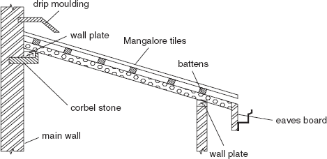
Figure 18.1 Lean to roof
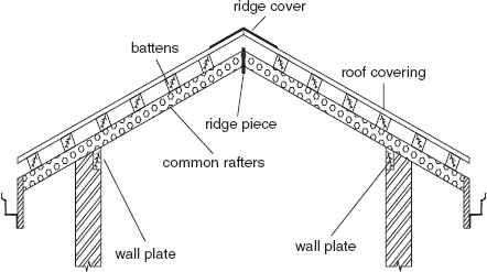
Figure 18.2 Couple roof
Collar beam roof
It is used for spans between 4 and 5.5 m. A collar of the same width as the rafter is fixed to every pair of rafters and it is attached at a height of half to one-third of the vertical height between the wall and the ridge. The collar is dovetailed with the rafter and the bolts can be used for additional safety. It is desirable to place the collar as low as possible to provide maximum strength to the roof (Figure 18.4).
Collar and tie roof
It is used when the roof spans exceed 5.5 m. It is a combination of collar beam roof and couple close roof. The rafters are supported by purlins and the purlins rest at the ends on walls. A collar and strut are employed to support the purlins and rafters. Its use is recommended when purlins may be supported at the ends with reasonable economy.
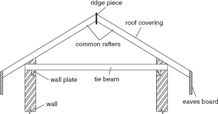
Figure 18.3 Couple close roof
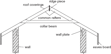
Figure 18.4 Collar beam roof
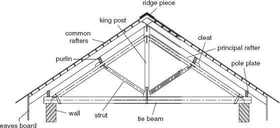
King post truss
For spans greater than 4.8 m, when no intermediate supporting walls for the purlins are available, framed structures known as trusses are used. The spacing between trusses is guided by the load coming on the roof, material of the truss, span and the location of cross walls.
In a king post truss, the central vertical post called as king post provides a support for the tie beam. The inclined members are known as struts and are used to prevent the principal rafters from bending at the centre. A king post truss can be used economically for spans 5–8 m.
The joint between the king post and the tie beam is an ordinary mortise and tenon joint. An iron stirrup is also provided to strengthen the joint further. For joining principal rafters and the king post, a tenon is cut in the principal rafter and the corresponding mortice into the head of the king post. A bridle joint is provided to connect the principal rafter with the tie beam. Joints between the king post and the strut are also mortice and tenon joints (Figure 18.5).
Queen post truss
It can be used for spans 9–14 m. It varies from the king post truss in having two vertical members known as queen posts. The heads of the queen posts are put apart by a horizontal member known as straining beam. The head of the queen post is made wider to receive the principal rafter and the straining beam. The top end of the principal rafter and the end of the straining beam are tenoned into the widened head of the queen posts. A three-way iron or mild steel strap is fixed to further strengthen the joint. The bottom end of the queen post is tenoned into the tie beam and a steel stirrup strap is fixed by jibs and cotters to make the joint stronger. The tenon of the inclined strut is inserted into the splayed shoulder of the queen post. The other joints in this truss are similar to that of the king post truss (Figure 18.6).
Mansard truss
It is a combination of king post truss and queen post truss. The upper portion has the shape of a king post truss and the lower portion resembles a queen post truss. The truss has two pitches. The upper pitch varies from 30 to 40° and the lower pitch varies from 60 to 70°. This type of truss is economical and in the span an extra room may be provided. This type of truss is now rarely used due to its ugly appearance. The construction of various joints is similar to that of the king post trusses.
Belfast roof trusses
This truss is in the form of a bow and is also called bow string or latticed roof truss. It is made of thin sections of timber. This truss can be used for big spans up to 30 m provided light roof coverings are used. The central rise in this type of truss is usually kept about one-eighth of the span.
Steel trusses
The use of steel trusses has become economical for spans greater than 12 m. Various standard shapes and sizes of rolled steel are available for the fabrication of steel trusses. This type of truss is designed in a manner that members are either in compression or in tension and bending stress is not allowed to develop in them.
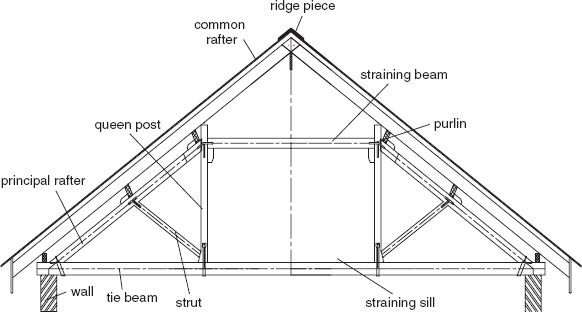
Figure 18.6 Queen post truss
The size and type of the truss depends upon the roof slope, span, centre-to-centre distance of the trusses and the load coming over the roof. T-sections are best suited for use as principal rafters, whereas angle iron or channel section is used as struts. The tension members should preferably be of a flat or round section. The different members of the truss may be fabricated with two or more sections joined together. The members of a truss are joined by rivets or bolts or by welding the plates known as gusset plates. The minimum spacing of the rivets should not be less than 3 times the diameter and the maximum spacing is limited to 15–20 cm in compression and tension members.
The minimum number of rivets to be used at any joint should not be less than two. Gusset plates are designed for the forces coming at the junction but the least thickness should be adopted as 6 mm. The ends of the trusses are placed on bed plates provided on the walls. The bed plate maybe of stone or concrete. The ends of the truss are bolted down with lewis or rag bolts which hold down the truss firmly. The small trusses are pre-fabricated in the workshop on the ground and are then placed in the required position. The bigger trusses are pre-fabricated in smaller parts and then erected in the required position and fixed by gusset plate and riveting or welding.
The relative advantage of steel roof trusses over timber sloping trusses are as follows:
- Steel sections forming the roof truss are light in weight and can be fabricated in different shapes and sizes. It suits the structural as well as architectural requirements.
- Steel trusses being made of mild steel sections are free from the attack of white ants and dry rot.
- Steel trusses are much stronger than timber trusses and they are equally strong in tension and compression.
- These trusses have a greater resistance against fire and hence are especially suited where fireproof construction is desired.
- Timber trusses can only be used up to a minimum span of 14 m or so, whereas there is no span restriction in case of steel trusses. Steel trusses are used for structures requiring large spans such as industrial buildings, large sheds, assembly halls, hangers and auditoriums.
- The various sections forming a steel truss can be easily machined and shaped in the workshop and subsequently packed and transported to the site for assembling. Moreover, there is no wastage in cutting.
- The erection of steel trusses from the rolled sections is very easy, rapid and economical.
Leave a Reply