We can represent a string wave (or any other type of wave) vectorially with a phasor. In essence, a phasor is a vector that has a magnitude equal to the amplitude of the wave and that rotates around an origin; the angular speed of the phasor is equal to the angular frequency ω of the wave. For example, the wave

is represented by the phasor shown in Fig. 16-17a. The magnitude of the phasor is the amplitude ym1 of the wave. As the phasor rotates around the origin at angular speed ω, its projection y1 on the vertical axis varies sinusoidally, from a maximum of ym1 through zero to a minimum of −ym1 and then back to ym1. This variation corresponds to the sinusoidal variation in the displacement y1 of any point along the string as the wave passes through that point.
When two waves travel along the same string in the same direction, we can represent them and their resultant wave in a phasor diagram. The phasors in Fig. 16-17b represent the wave of Eq. 16-55 and a second wave given by

This second wave is phase-shifted from the first wave by phase constant ![]() . Because the phasors rotate at the same angular speed ω, the angle between the two phasors is always
. Because the phasors rotate at the same angular speed ω, the angle between the two phasors is always ![]() . If
. If ![]() is a positive quantity, then the phasor for wave 2 lags the phasor for wave 1 as they rotate, as drawn in Fig. 16-17b. If
is a positive quantity, then the phasor for wave 2 lags the phasor for wave 1 as they rotate, as drawn in Fig. 16-17b. If ![]() is a negative quantity, then the phasor for wave 2 leads the phasor for wave 1.
is a negative quantity, then the phasor for wave 2 leads the phasor for wave 1.
Because waves y1 and y2 have the same angular wave number k and angular frequency ω, we know from Eqs. 16-51 and 16-52 that their resultant is of the form

where ![]() is the amplitude of the resultant wave and β is its phase constant. To find the values of
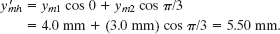
is the amplitude of the resultant wave and β is its phase constant. To find the values of ![]() and β, we would have to sum the two combining waves, as we did to obtain Eq. 16-51. To do this on a phasor diagram, we vectorially add the two phasors at any instant during their rotation, as in Fig. 16-17c where phasor ym2 has been shifted to the head of phasor ym1. The magnitude of the vector sum equals the amplitude
and β, we would have to sum the two combining waves, as we did to obtain Eq. 16-51. To do this on a phasor diagram, we vectorially add the two phasors at any instant during their rotation, as in Fig. 16-17c where phasor ym2 has been shifted to the head of phasor ym1. The magnitude of the vector sum equals the amplitude ![]() in Eq. 16-57. The angle between the vector sum and the phasor for y1 equals the phase constant β in Eq. 16-57.
in Eq. 16-57. The angle between the vector sum and the phasor for y1 equals the phase constant β in Eq. 16-57.
Note that, in contrast to the method of Section 16-10:
![]() We can use phasors to combine waves even if their amplitudes are different.
We can use phasors to combine waves even if their amplitudes are different.
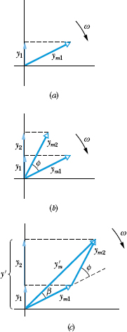
Fig. 16-17 (a) A phasor of magnitude ym1 rotating about an origin at angular speed ω represents a sinusoidal wave. The phasor’s projection y1 on the vertical axis represents the displacement of a point through which the wave passes. (b) A second phasor, also of angular speed ω but of magnitude ym2 and rotating at a constant angle ![]() from the first phasor, represents a second wave, with a phase constant
from the first phasor, represents a second wave, with a phase constant ![]() . (c) The resultant wave is represented by the vector sum
. (c) The resultant wave is represented by the vector sum ![]() of the two phasors.
of the two phasors.
Two sinusoidal waves y1 (x, t) and y2(x, t) have the same wavelength and travel together in the same direction along a string. Their amplitudes are ym1 = 4.0 mm and ym2 = 3.0 mm, and their phase constants are 0 and π/3 rad, respectively. What are the amplitude ![]() and phase constant β of the resultant wave? Write the resultant wave in the form of Eq. 16-57.
and phase constant β of the resultant wave? Write the resultant wave in the form of Eq. 16-57.
Solution: One Key Idea here is that the two waves have a number of properties in common: Because they travel along the same string, they must have the same speed v, as set by the tension and linear density of the string according to Eq. 16-26. With the same wavelength λ, they must have the same angular wave number k (= 2π/λ). Also, with the same wave number k and speed v, they must have the same angular frequency ω (= kv).
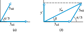
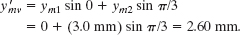
Fig. 16-18 (a) Two phasors of magnitudes ym1 and ym2 and with phase difference π/3. (b) Vector addition of these phasors at any instant during their rotation gives the magnitude ![]() of the phasor for the resultant wave.
of the phasor for the resultant wave.
A second Key Idea is that the waves (call them waves 1 and 2) can be represented by phasors rotating at the same angular speed ω about an origin. Because the phase constant for wave 2 is greater than that for wave 1 by π/3, phasor 2 must lag phasor 1 by π/3 rad in their clockwise rotation, as shown in Fig. 16-18a. The resultant wave due to the interference of waves 1 and 2 can then be represented by a phasor that is the vector sum of phasors 1 and 2.
To simplify the vector summation, we drew phasors 1 and 2 in Fig. 16-18a at the instant when phasor 1 lies along the horizontal axis. We then drew lagging phasor 2 at positive angle π/3 rad. In Fig. 16-18b we shifted phasor 2 so its tail is at the head of phasor 1. Then we can draw the phasor ![]() of the resultant wave from the tail of phasor 1 to the head of phasor 2. The phase constant β is the angle phasor
of the resultant wave from the tail of phasor 1 to the head of phasor 2. The phase constant β is the angle phasor ![]() makes with phasor 1.
makes with phasor 1.
To find values for ![]() and β, we can sum phasors 1 and 2 directly on a vector-capable calculator (by adding a vector of magnitude 4.0 and angle 0 rad to a vector of magnitude 3.0 and angle π/3 rad) or we can add the vectors by components. For the horizontal components we have
and β, we can sum phasors 1 and 2 directly on a vector-capable calculator (by adding a vector of magnitude 4.0 and angle 0 rad to a vector of magnitude 3.0 and angle π/3 rad) or we can add the vectors by components. For the horizontal components we have
For the vertical components we have
Thus, the resultant wave has an amplitude of
and a phase constant of
From Fig. 16-18b, phase constant β is a positive angle relative to phasor 1. Thus, the resultant wave lags wave 1 in their travel by phase constant β = +0.44 rad. From Eq. 16-57, we can write the resultant wave as

Leave a Reply