When a large number of atoms come together to form a metallic solid, such as an iron nail, they settle into equilibrium positions in a three-dimensional lattice, a repetitive arrangement in which each atom is a well-defined equilibrium distance from its nearest neighbors. The atoms are held together by interatomic forces that are modeled as tiny springs in Fig. 12-10. The lattice is remarkably rigid, which is another way of saying that the “interatomic springs” are extremely stiff. It is for this reason that we perceive many ordinary objects, such as metal ladders, tables, and spoons, as perfectly rigid. Of course, some ordinary objects, such as garden hoses or rubber gloves, do not strike us as rigid at all. The atoms that make up these objects do not form a rigid lattice like that of Fig. 12-10 but are aligned in long, flexible molecular chains, each chain being only loosely bound to its neighbors.
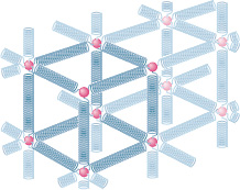
Fig. 12-10 The atoms of a metallic solid are distributed on a repetitive three-dimensional lattice. The springs represent interatomic forces.
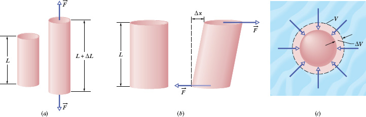
Fig. 12-11 (a) A cylinder subject to tensile stress stretches by an amount ΔL. (b) A cylinder subject to shearing stress deforms by an amount Δx, somewhat like a pack of playing cards would. (c) A solid sphere subject to uniform hydraulic stress from a fluid shrinks in volume by an amount ΔV. All the deformations shown are greatly exaggerated.
All real “rigid” bodies are to some extent elastic, which means that we can change their dimensions slightly by pulling, pushing, twisting, or compressing them. To get a feeling for the orders of magnitude involved, consider a vertical steel rod 1 m long and 1 cm in diameter attached to a factory ceiling. If you hang a subcompact car from the free end of such a rod, the rod will stretch but only by about 0.5 mm, or 0.05%. Furthermore, the rod will return to its original length when the car is removed.
If you hang two cars from the rod, the rod will be permanently stretched and will not recover its original length when you remove the load. If you hang three cars from the rod, the rod will break. Just before rupture, the elongation of the rod will be less than 0.2%. Although deformations of this size seem small, they are important in engineering practice. (Whether a wing under load will stay on an airplane is obviously important.)
Figure 12-11 shows three ways in which a solid might change its dimensions when forces act on it. In Fig. 12-11a, a cylinder is stretched. In Fig. 12-11b, a cylinder is deformed by a force perpendicular to its long axis, much as we might deform a pack of cards or a app. In Fig. 12-11c, a solid object placed in a fluid under high pressure is compressed uniformly on all sides. What the three deformation types have in common is that a stress, or deforming force per unit area, produces a strain, or unit deformation. In Fig. 12-11, tensile stress (associated with stretching) is illustrated in (a), shearing stress in (b), and hydraulic stress in (c).

Fig. 12-12 A test specimen used to determine a stress–strain curve such as that of Fig. 12-13. The change ΔL that occurs in a certain length L is measured in a tensile stress–strain test.
The stresses and the strains take different forms in the three situations of Fig. 12-11, but—over the range of engineering usefulness—stress and strain are proportional to each other. The constant of proportionality is called a modulus of elasticity, so that

In a standard test of tensile properties, the tensile stress on a test cylinder (like that in Fig. 12-12) is slowly increased from zero to the point at which the cylinder fractures, and the strain is carefully measured and plotted. The result is a graph of stress versus strain like that in Fig. 12-13. For a substantial range of applied stresses, the stress–strain relation is linear, and the specimen recovers its original dimensions when the stress is removed; it is here that Eq. 12-22 applies. If the stress is increased beyond the yield strength Sy of the specimen, the specimen becomes permanently deformed. If the stress continues to increase, the specimen eventually ruptures, at a stress called the ultimate strength Su.
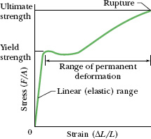
Fig. 12-13 A stress–strain curve for a steel test specimen such as that of Fig. 12-12. The specimen deforms permanently when the stress is equal to the yield strength of the specimen’s material. It ruptures when the stress is equal to the ultimate strength of the material.
Tension and Compression
For simple tension or compression, the stress on the object is defined as F/A, where F is the magnitude of the force applied perpendicularly to an area A on the object. The strain, or unit deformation, is then the dimensionless quantity ΔL/L, the fractional (or sometimes percentage) change in a length of the specimen. If the specimen is a long rod and the stress does not exceed the yield strength, then not only the entire rod but also every section of it experiences the same strain when a given stress is applied. Because the strain is dimensionless, the modulus in Eq. 12-22 has the same dimensions as the stress—namely, force per unit area.
The modulus for tensile and compressive stresses is called the Young’s modulus and is represented in engineering practice by the symbol E. Equation 12-22 becomes
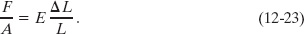
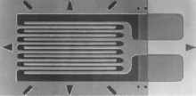
Fig. 12-14 A strain gage of overall dimensions 9.8 mm by 4.6 mm. The gage is fastened with adhesive to the object whose strain is to be measured; it experiences the same strain as the object. The electrical resistance of the gage varies with the strain, permitting strains up to 3% to be measured. Courtesy Vishay Micro-Measurements Group, Inc., Raleigh, NC, USA.
The strain ΔL/L in a specimen can often be measured conveniently with a strain gage (Fig. 12-14). This simple and useful device, which can be attached directly to operating machinery with an adhesive, is based on the principle that its electrical properties are dependent on the strain it undergoes.
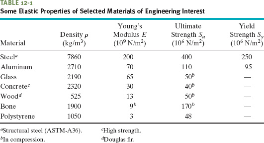
Although the Young’s modulus for an object may be almost the same for tension and compression, the object’s ultimate strength may well be different for the two types of stress. Concrete, for example, is very strong in compression but is so weak in tension that it is almost never used in that manner. Table 12-1 shows the Young’s modulus and other elastic properties for some materials of engineering interest.
Shearing
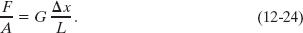
In the case of shearing, the stress is also a force per unit area, but the force vector lies in the plane of the area rather than perpendicular to it. The strain is the dimensionless ratio Δx/L, with the quantities defined as shown in Fig. 12-11b. The corresponding modulus, which is given the symbol G in engineering practice, is called the shear modulus. For shearing, Eq. 12-22 is written as
Shearing stresses play a critical role in the buckling of shafts that rotate under load and in bone fractures caused by bending.
Hydraulic Stress
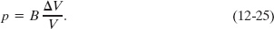
In Fig. 12-11c, the stress is the fluid pressure p on the object, and, as you will see in Lesson 14, pressure is a force per unit area. The strain is ΔV/V, where V is the original volume of the specimen and ΔV is the absolute value of the change in volume. The corresponding modulus, with symbol B, is called the bulk modulus of the material. The object is said to be under hydraulic compression, and the pressure can be called the hydraulic stress. For this situation, we write Eq. 12-22 as
The bulk modulus is 2.2 × 10⁹ N/m2 for water and 1.6 × 10¹¹ N/m2 for steel. The pressure at the bottom of the Pacific Ocean, at its average depth of about 4000 m, is 4.0 × 10⁷ N/m2. The fractional compression ΔV/V of a volume of water due to this pressure is 1.8%; that for a steel object is only about 0.025%. In general, solids—with their rigid atomic lattices—are less compressible than liquids, in which the atoms or molecules are less tightly coupled to their neighbors.
Sample Problem 12-5
A steel rod has a radius R of 9.5 mm and a length L of 81 cm. A 62 kN force ![]() stretches it along its length. What are the stress on the rod and the elongation and strain of the rod?
stretches it along its length. What are the stress on the rod and the elongation and strain of the rod?
Solution: The first Key Idea here has to do with what is meant by the second sentence in the problem statement. We assume the rod is held stationary by, say, a clamp or vise at one end. Then force ![]() is applied at the other end, parallel to the length of the rod and thus perpendicular to the end face there. Therefore, the situation is like that in Fig. 12-11a.
is applied at the other end, parallel to the length of the rod and thus perpendicular to the end face there. Therefore, the situation is like that in Fig. 12-11a.
The next Key Idea is that we assume the force is applied uniformly across the end face and thus over an area A = πR2. Then the stress on the rod is given by the left side of Eq. 12-23:
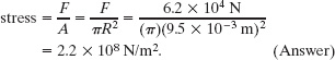
The yield strength for structural steel is 2.5 × 10⁸ N/m2, so this rod is dangerously close to its yield strength.
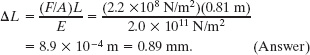
Another Key Idea is that the elongation of the rod depends on the stress, the original length L, and the type of material in the rod. The last determines which value we use for Young’s modulus E (from Table 12-1). Using the value for steel, Eq. 12-23 gives us
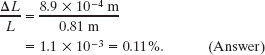
The last Key Idea we need here is that strain is the ratio of the change in length to the original length, so we have
Sample Problem 12-6
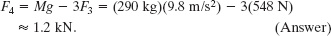
A table has three legs that are 1.00 m in length and a fourth leg that is longer by d = 0.50 mm, so that the table wobbles slightly. A steel cylinder with mass M = 290 kg is placed on the table (which has a mass much less than M) so that all four legs are compressed but unbuckled and the table is level but no longer wobbles. The legs are wooden cylinders with cross-sectional area A = 1.0 cm2; Young’s modulus is E = 1.3 × 10¹⁰ N/m2. What are the magnitudes of the forces on the legs from the floor?
Solution: We take the table plus steel cylinder as our system. The situation is like that in Fig. 12-9, except now we have a steel cylinder on the table. One Key Idea is that if the table-top remains level, the legs must be compressed in the following ways: Each of the short legs must be compressed by the same amount (call it ΔL3) and thus by the same force of magnitude F3. The single long leg must be compressed by a larger amount ΔL4 and thus by a force with a larger magnitude F4. In other words, for a level tabletop, we must have

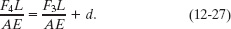
A second Key Idea is that, from Eq. 12-23, we can relate a change in length to the force causing the change with ΔL = FL/AE, where L is the original length of a leg. We can use this relation to replace ΔL4 and ΔL3 in Eq. 12-26. However, note that we can approximate the original length L as being the same for all four legs. The replacements then give us
We cannot solve this equation because it has two unknowns, F4 and F3.
To get a second equation containing F4 and F3, we can use a vertical y axis and then write the balance of vertical forces (Fnet,y = 0) as

where Mg is equal to the magnitude of the gravitational force on the system. (Three legs have force ![]() on them.) To solve the simultaneous equations 12-27 and 12-28 for, say, F3, we first use Eq. 12-28 to find that F4 = Mg − 3F3. Substituting that into Eq. 12-27 then yields, after some algebra,
on them.) To solve the simultaneous equations 12-27 and 12-28 for, say, F3, we first use Eq. 12-28 to find that F4 = Mg − 3F3. Substituting that into Eq. 12-27 then yields, after some algebra,
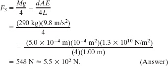
From Eq. 12-28 we then find
You can show that to reach their equilibrium configuration, the three short legs are each compressed by 0.42 mm and the single long leg by 0.92 mm.
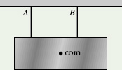
![]() CHECKPOINT 6 The figure shows a horizontal block that is suspended by two wires, A and B, which are identical except for their original lengths. The center of mass of the block is closer to wire B than to wire A. (a) Measuring torques about the block’s center of mass, state whether the magnitude of the torque due to wire A is greater than, less than, or equal to the magnitude of the torque due to wire B. (b) Which wire exerts more force on the block? (c) If the wires are now equal in length, which one was originally shorter?
CHECKPOINT 6 The figure shows a horizontal block that is suspended by two wires, A and B, which are identical except for their original lengths. The center of mass of the block is closer to wire B than to wire A. (a) Measuring torques about the block’s center of mass, state whether the magnitude of the torque due to wire A is greater than, less than, or equal to the magnitude of the torque due to wire B. (b) Which wire exerts more force on the block? (c) If the wires are now equal in length, which one was originally shorter?
Leave a Reply